

UML Notation
Version 1.4


Version 1.4
A class diagram (also called a static object model) is a graphical view of the static structural model, in particular, the things that exist (such as classes and types), their internal structure, and their relationships to other things. Class diagrams do not show temporal information.
 |
Classes, Objects and Interfaces Either or both of the attribute and operation compartments may be suppressed (a separator line is not drawn for a missing compartment). Attributes (types, default values,...) and operations (arguments, return type,...) can be specified in general UML syntax or in a language specific syntax, such as C++ or Java.
Names of abstract classes and operations are shown in italic (or are followed by the constraint {abstract}). Names of interface operations are abstract by default and must not necessarily be written in italic. Note: In C++ an interface is a class containing nothing but pure virtual functions. Objects can specify their object name and their class name or just one of both (but the colon must always be written). |
||||||||||||||||||||
|
UML also allows Microsoft-style interface notation, which hides all interface details. A utility class is a class with only class-scope attributes and operations, therefore it is not necessary to underline them. Other stereotypes that can be used within a class rectangle: «exception» |
|
Parameterised classes A parameterised class (or template class or generic class) is also supported in UML, although it does not exist in Java (in Java, one should use the fact that all classes are derived from a common Object class or stated otherwise: Java is single rooted). |
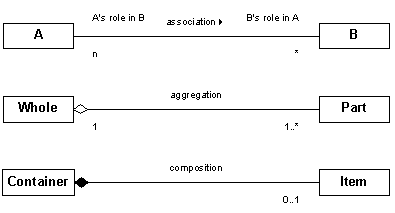 |
Associations Aggregation is a strong form of association that specifies a shared whole-part relation. Composition is a strong form of aggregation which requires that a part instance be included in at most one composite at a time (unshared: cardinality at the diamond side can be dropped because it is always exactly 1) and that the parts are destroyed along with the whole (cascading delete).
In implementation diagrams, the navigability of the message flow along the relationship can be shown with a shallow arrowhead at the association end. |
||||||||||||
|
Constrained associations If the cardinality of an association is greater than one, the elements can be ordered or unordered (the default). An ordered collection can be indicated with a constraint. It is possible to have more than one associations between the same classes. When one association is a subset of the other, it can be indicated with a constraint. When only one of two possible associations can hold, an or-association can be used (noted as a constraint). |
||||||||||||
|
Association class An association class is an association that has its own set of features (attributes and operations). Of an association class there can be at most one object for each unique couple objects from the associations (e.g. for each unique combination of a Person object and a Workstation object, there can only be exactly one Authorisation object). |
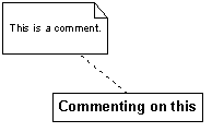 |
Comments A comment can attach arbitrary textual information to any model element, such as reasons for design decisions, implementation-level code, references to documents,... |
 |
Relationships Realisation: The client only supports the inherited operations of the supplier and not the structure (attributes and associations). This is used between a class and an interface (the class realises or supports the interface). Generalisation: The subclass fully supports all features of the superclass, including all inherited attributes, associations and operations. This relationship can be used to extend a class as well as an interface. Dependency: The target element could be affected by changes in the source element (e.g., the class has a local variable or operation argument of some resource class). Dependencies can exist between objects, classes, interfaces, packages,... or even between operations. A stereotype can give more information about the kind of dependency: «instance», «use», «access», «import», «friend» |
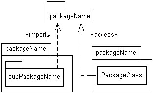 |
UML Packages An UML package is a grouping of model elements (all UML model elements can be organised into packages) with similar functionality. Packages can also be nested within each other. In class diagrams, UML packages correspond to a Java packages or C++ namespaces. A package name is always part of the (fully qualified) class name:
|
 |
Design patterns Note: The singleton and facade design pattern can be shown as a stereotype on respectively the class and package icons. |
| {constraint} | Constraints A constraint is a semantic relationship among model elements that specifies conditions and propositions that must be maintained as true. Predefined constraints:
|
| «stereotype» | Stereotypes A stereotype is a user-defined meta element. Some stereotypes are predefined...
|
A use case diagram depicts what services the system provides to the user and gives information about the users (actors) or the system. It reflects the requirements of the system.
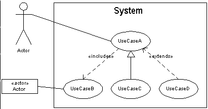 |
Actor: An actor represents a role that a user, anything outside the system that will interact with the system, plays. It can be a person or another system. Use case: A use case describes the transactions, the functionality, offered by the system (what the system must provide, rather than how). A use case is initiated by an actor. Dependency: A dependency between use cases can indicate either an include (the behavior defined in the target use case is included at one location in the sequence of behavior performed by the base use case) or an extend (a use case may be augmented with some additional behavior defined in another use case) dependency. Generalisation: A generalisation from use case A to use case B indicates that A is a specialisation of B. |
An interaction diagram (dynamic model) shows the (dynamic) message flow between the objects (and actors).
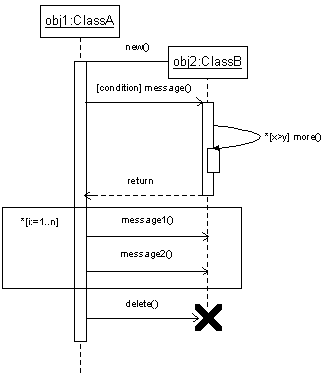 |
Sequence diagram A sequence diagram shows an interaction (exchange of messages) arranged in time sequence. Horizontally, the participating instances (objects or actors) are shown by their lifeline, the vertical dimension is the time axis. An activation (tall thin rectangle) shows the period during which an object is performing an action either directly or through a subordinate procedure. A branch is shown by multiple arrows leaving a single point; each possibly labeled by a condition specified between square brackets. A loop is depicted by grouping the repeated messages in a rectangler box and an asterisk (*) in front of the loop condition. Collaboration diagram The interactions between objects can also be shown in another form that puts more emphasis on the collaborations instead of timing issues. |
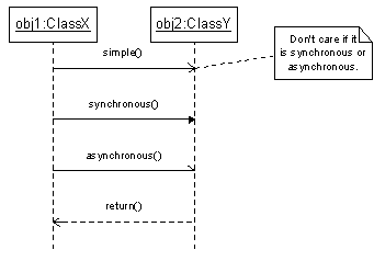 |
Message types A simple message is used for asynchronous messages or when the difference between a synchronous and asynchronous message is not important. A synchronous message blocks the caller till the message returns. In a procedural flow of control, the return message may be omitted. The notation with a half arrowhead is deprecated in UML 1.4. |
A statechart diagram can be used to describe the behavior of a model element (mostly a class). It describes possible sequences of states and actions through which the element can proceed during its lifetime as a result of reacting to discrete events (e.g. operation invocations). A statechart diagram is a graph that represents a state machine.
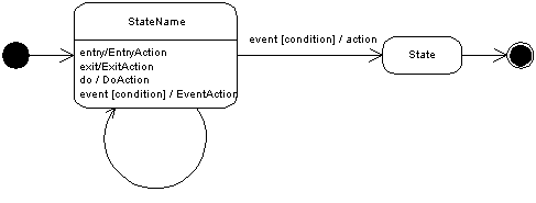 |
States A state is a condition of an object during which it satisfies some conditions, performs actions and waits for events. An event triggers a transition from one state to another. Entry and exit actions are automatically performed when the state is entered or left. Do actions are performed as long as the state is active or until the computation of the specified action is finished. Events written inside the state element trigger internal state transitions which are equivalent with self-transitions except that the state is not exited and re-entered. |
|
|
Composite states A composite state is a state that is decomposed into two or more concurrent substates or into mutually exclusive disjoint substates. The internal details of a composite state can be hidden using a special icon under the name of the state. |
![]()
![]()
|
Andy Verkeyn's Website, © Andy Verkeyn 1997-2015 Last webpage revision: |